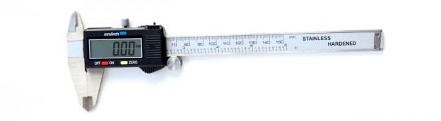
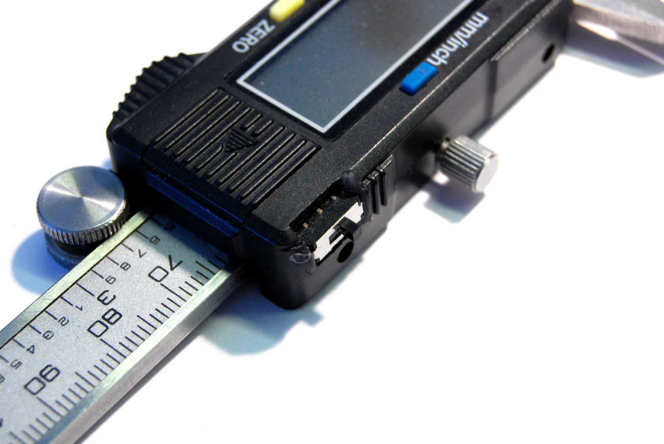
Digital calipers are wonderful. Once I bought my first set, it was hard to resist the urge to go measure all the things.
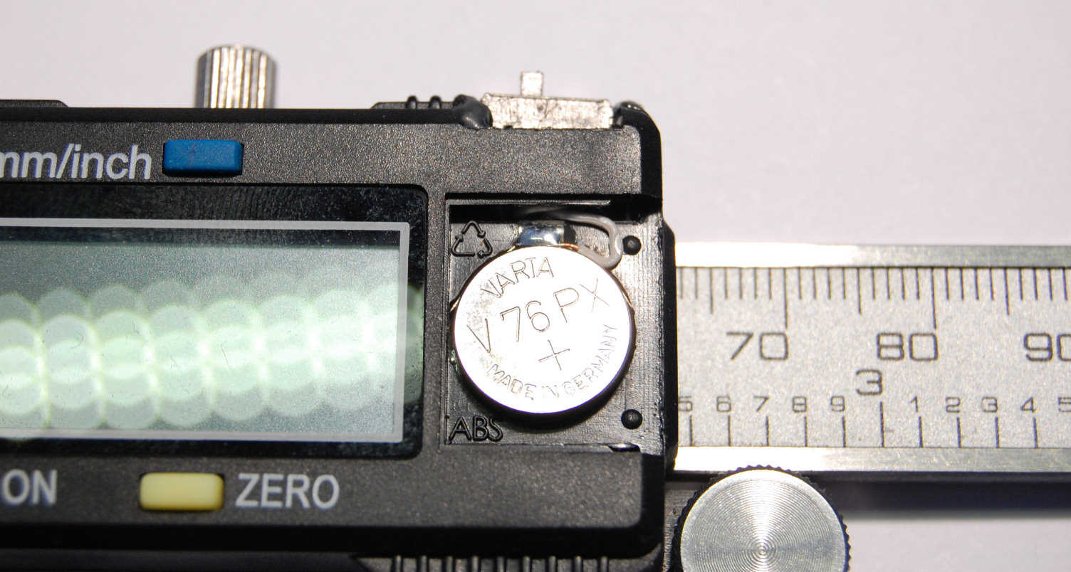
They are useful until the battery dies. The engineer in me gasps in horror when it realizes that the calipers never completely turn off; in fact, it is only the display that turns off, leaving the LR44 battery draining happily, pushing electrons through the rest of the circuit, 24/7. To be fair, the more expensive models lack this always-on “feature”, but let’s be honest. When was the last time you bought a $100 pair of calipers when you could instead get virtually the same for $15, even when you knew the battery life was numbered in months instead of years?
Once the battery drained, I had two options: replace the battery, or improve the design. Replacing the battery would mean using the spare LR44 that was thoughtfully included with the calipers in the original packaging, and then periodically buying more of the same to keep up with the drain.
I decided to improve the design. Who likes to constantly run out and buy new batteries?
Goal: improve the design in as invisible a way as possible.
I have seen a few hacks done by other people which involved adding an external battery with an on-off switch, but that method ended up doubling the size of the measuring module (https://www.sparkfun.com/tutorials/362).
Someone else has solved the problem by replacing the battery with a supercapacitor (http://hackaday.com/2013/08/08/supercharging-your-digital-calipers/) I guess charging it for 20 seconds every 3 days (or whenever you need to use it) is better than replacing the battery every few months and having to buy more replacements, but it still means attaching a very big capacitor to the module.
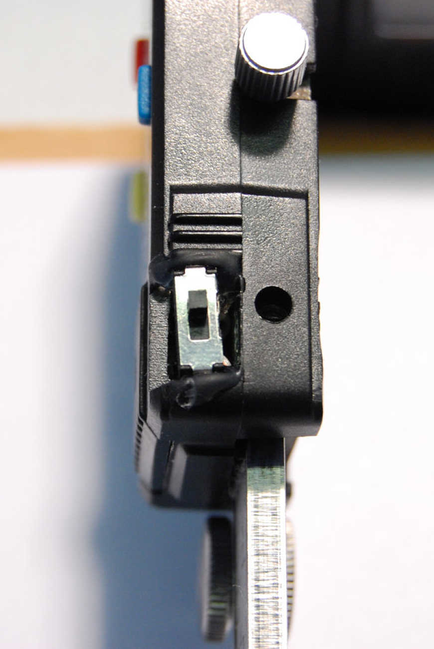
My plan was simply to add an on-off switch to the case. I had in stock a DPDT switch small enough to fit inside the data port window along the top edge of the case.
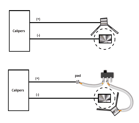
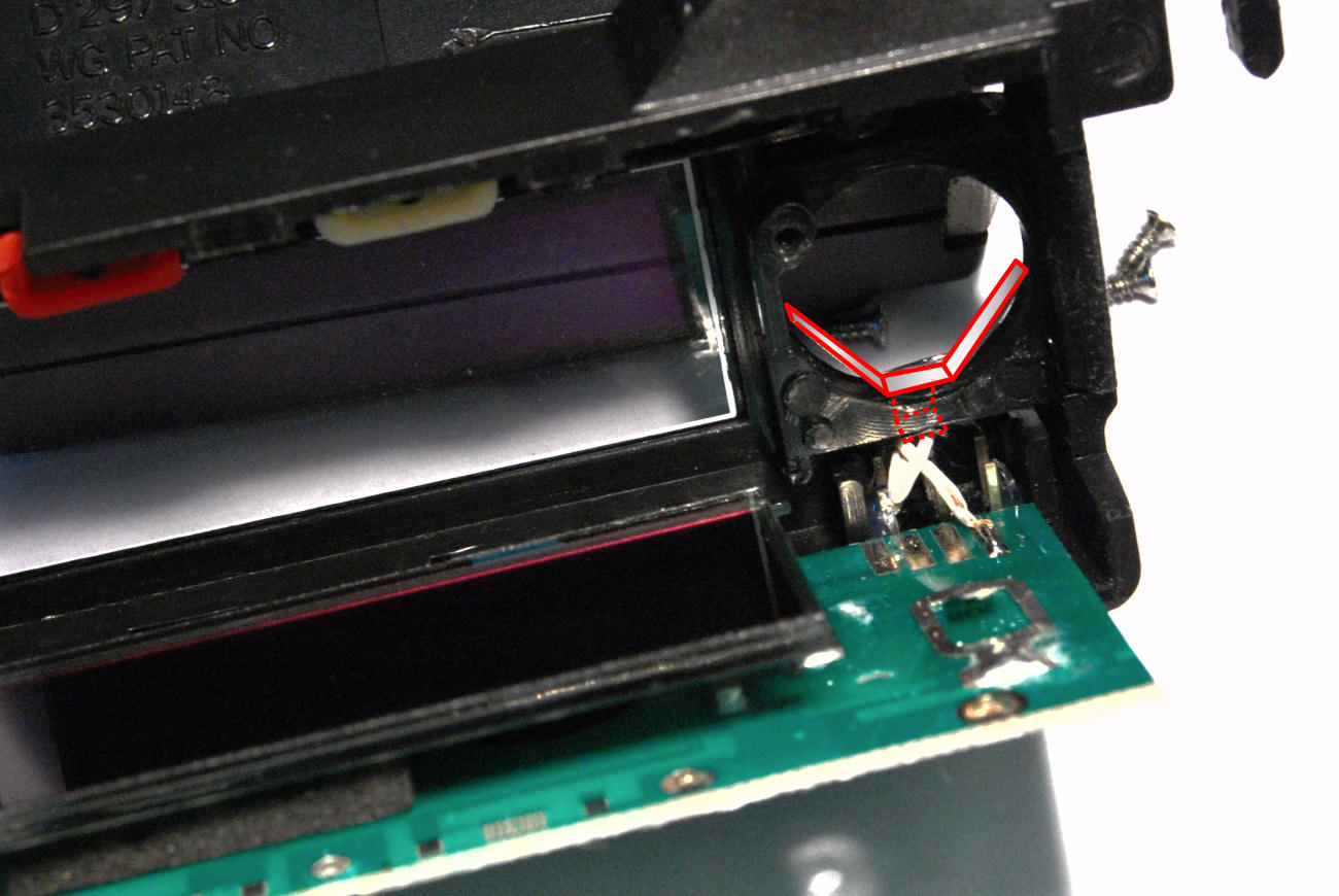
To do this, I had to insert the switch into the circuit between the battery and the module. First, I de-soldered the angled battery clip (positive) from the circuit board. The photo below shows where the battery clip was originally attached.
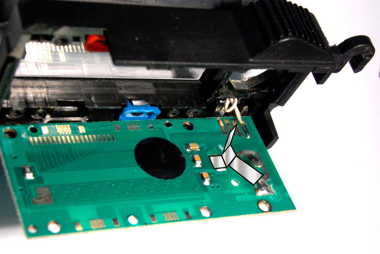
Probing with a multimeter, I found a pad in the data interface connected to the battery positive pad, which I had just de-soldered. I soldered a wire to this new pad.
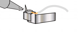
To fit back in the case, the battery clip had to be installed in a different orientation. To do this, I bent the solder tab at a 90 degree angle a couple of millimeters down the tab, like this.
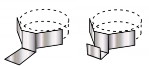
Then, I soldered another wire to the tab on the battery clip.
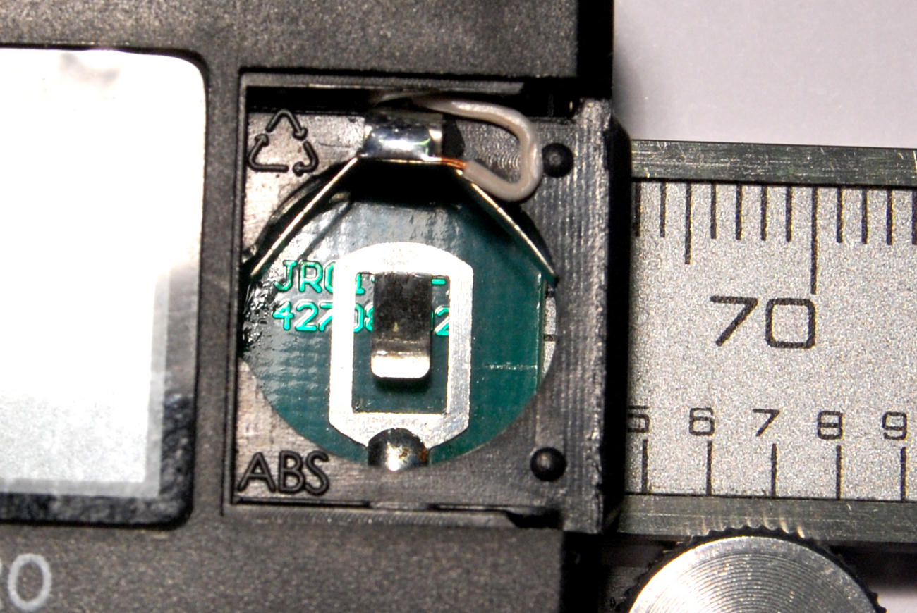
I could now fit the clip back into the case by fitting the bent solder tab over the plastic bridge just above the battery pocket. Originally, the clip was soldered directly to the circuit board, but now it was upside-down and inserted through the top of the case. I added a drop of superglue between the inside surface of the solder tab and fit it onto the plastic bridge.
I threaded the free ends of the two wires out through the data port window in the side of the case, and soldered them to the switch. Finally, I pushed the wires inside the case and glued the switch into the data port window using hot glue. Finished.
Thanks, this is a good hack and should be on youtube 🙂
Awesome idea to flip the battery clip upside down!